

Introduction
When specifying high-performance ventilation setups for manufacturing lines, commercial warehouses, or complex chemical treatment environments, selecting equipment strictly based on how fast an impeller turns is a critical miscalculation. A highly functional industrial air handling system balances two fundamental, contrasting physical properties: Airflow and Static Pressure.
While these two engineering metrics share an inverse relationship along any operational performance loop, they govern entirely separate characteristics of air movement. Failing to properly configure high-capacity equipment to handle localized friction parameters can lead to system performance degradation, high energy waste, localized overheating, or premature fan motor burnout.
Breaking Down Airflow (CFM)
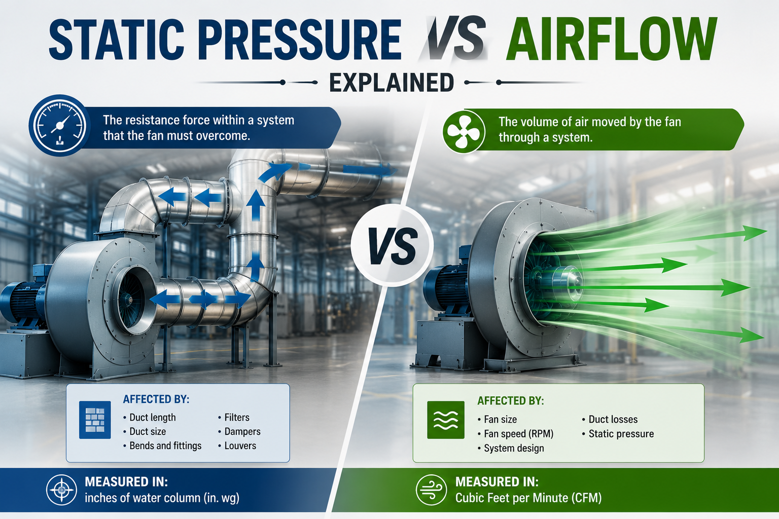
Airflow defines the absolute quantitative volume of air an industrial fan assembly moves through an open path over a specific duration. In standard international engineering frameworks, this characteristic is measured via Cubic Feet per Minute (CFM) or Cubic Meters per Hour (m³/h).
CFM profiles describe the pure refreshing velocity or volume sweeping across a room or open industrial zone. High-CFM hardware provides substantial continuous air renewal, making it ideal for large spaces where minimal resistance exists. In simple contexts, think of airflow as the absolute quantity of air passing through a wide pipeline.
Demystifying Static Pressure
Static pressure represents the persistent resistance or frictional force exerted by conduits, protective screens, filtration banks, localized dampers, or internal machinery enclosures against moving air. Usually quantified in inches of water gauge (in. WG), millimeters of water column (mmWC), or Pascals (Pa), static pressure acts as a directional bottleneck.
To apply an aerodynamic analogy: if airflow represents the total volume of water running through a commercial pipeline, static pressure is the exact pushback force generated when narrowing down the outlet nozzle. When an air pathway features dense component layouts, long straight duct lengths, or tight directional turns, the system's static pressure values climb sharply.
The Balancing Act: The System Performance Curve
Industrial air handling systems perform dynamically on a sliding scale. As localized structural resistance (static pressure) inside a system duct layout climbs, the total volume output (CFM) drops. Conversely, maximizing pure CFM capacity requires minimizing obstacles, which drops static pressure to near zero.
If an installer positions a standard high-CFM exhaust system in a layout choked by fine dust extraction filters or restricted ducts, the assembly will encounter an aerodynamic bottleneck. Unable to fight the massive static pressure, the fan will drop its net volumetric displacement, stall out, consume excessive energy, and eventually overheat due to structural resistance.
Aerodynamic Profiles by Equipment Category
Different manufacturing layouts demand targeted airflow profiles to optimize efficiency. The following functional matrix contrasts common configurations across heavy-duty equipment categories:
| Fan Configuration Type | Airflow Capacity (CFM) | Static Pressure Capability | Primary System Application |
|---|---|---|---|
| Industrial Centrifugal Blowers | Moderate to High Profiles | Extremely High (Up to 20+ in. WG) | Ducted systems, filter houses, material transport loops |
| Tube Axial Fan Assemblies | High Continuous Volumetric Flow | Medium to Low Pressure Curves | Straight inline duct exhausts, paint booths, stack vents |
| Heavy Duty Exhaust Fans | Very High Mass Flow Rates | Low Resistance Thresholds | Wall-mounted factory cooling, unstructured open venting |
| High Volume Low Speed (HVLS) Fans | Massive Sweeping Volumes | Near Zero Operational Resistance | Open-space commercial warehouses, indoor assembly bays |
How to Properly Size Systems for Frictional Resistance
To guarantee continuous system longevity, plant planners must run systematic sizing calculations:
- Calculate Total System Resistance: Compile the physical pressure drops across every individual element, including long duct runs, filter modules, louvers, and transformation bends.
- Examine Manufacturer Fan Curves: Ensure the chosen model delivers the necessary target CFM exactly at the calculated peak operational static pressure point, rather than checking unconstrained maximum capabilities alone.
- Account for Variable Load Factors: Filtration banks collect debris during regular operation, which spikes system static pressure. Select equipment with adequate capacity headroom to maintain required air change rates as components age.
Conclusion
Mastering the interplay between static pressure and airflow removes the guesswork from specifying heavy-duty industrial ventilation. Sizing systems based on unconstrained mass flow ratings alone creates systemic vulnerabilities, whereas coordinating pressure development guarantees stable thermal control.
Optimizing complex industrial duct loops requires precise mechanical matching. Alfa Fans manufactures robust industrial centrifugal blowers, dynamic tube axial assemblies, and high-efficiency ventilation setups engineered to handle demanding structural resistance environments. By coordinating precision dynamically balanced impellers with heavy-duty structural enclosures, Alfa Fans delivers reliable air management customized to your precise operational demands.