

Centrifugal Blower Discharge Position and Rotation: How to Specify the Right Arrangement for Your Duct Layout
- 5 November 2026
- Alfa Fans
- Blog
The centrifugal blower discharge position is the direction the fan outlet faces, always stated together with the direction of impeller rotation viewed from the drive side, for example "clockwise, top horizontal" (CW TH). To specify it correctly, stand on the drive side of where the blower will sit, follow the duct that leaves the outlet, and choose the rotation and outlet angle that point straight into that duct. Getting this right on the purchase order avoids site modifications, extra elbows and lost static pressure.
Many enquiries for centrifugal blowers arrive with the air volume and pressure defined but the arrangement left blank. The fan is then built, delivered and found to point the wrong way. This guide explains the naming convention, how it connects to your duct layout and what information to send when you request a quotation.
What Rotation and Discharge Position Mean on Centrifugal Fans
Every centrifugal blower fan has a scroll-shaped housing that collects air thrown outward by the impeller and guides it to a single outlet. Because the scroll spirals in one direction only, the impeller must turn in that direction, and the outlet can only sit at certain points around the housing. Rotation and discharge position together describe the physical hand of the fan.
How rotation is determined
Rotation is judged from the drive side of the fan. On a single-inlet blower, this is the side opposite the inlet, where the motor or pulley is mounted. On a double-width, double-inlet blower, it is the side carrying the drive. If the impeller turns clockwise as you face it from that side, the fan is clockwise (CW); if not, it is counter-clockwise (CCW). This convention is set out by the Air Movement and Control Association International (AMCA) in AMCA Standard 99-2406, which is widely used by industrial centrifugal fans suppliers and consultants as a common reference. The most frequent error on site is viewing the fan from the inlet side, which reverses the answer.
The standard discharge positions
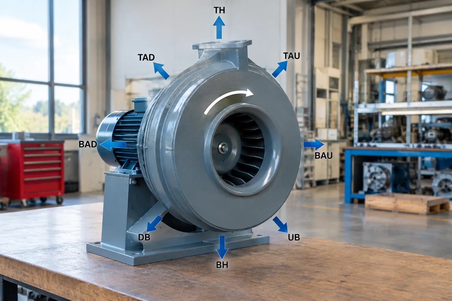
Under the same AMCA convention, the outlet is described by where it sits on the housing and which way the air leaves it:
- Top horizontal (TH): outlet at the top, air leaving horizontally.
- Bottom horizontal (BH): outlet at the bottom, air leaving horizontally.
- Up blast (UB): air discharging vertically upward.
- Down blast (DB): air discharging vertically downward.
- Top angular up (TAU) and top angular down (TAD): outlet angled upward or downward from the top.
- Bottom angular up (BAU) and bottom angular down (BAD): outlet angled upward or downward from the bottom.
Combined with CW or CCW rotation, these positions give sixteen possible arrangements. For belt-driven units, motor location is a separate designation: AMCA Standard 99-2407 uses the letters W, X, Y and Z to describe where the motor sits relative to the fan, again viewed from the drive side.
Why the Centrifugal Blower Discharge Position Matters for Your Duct Layout
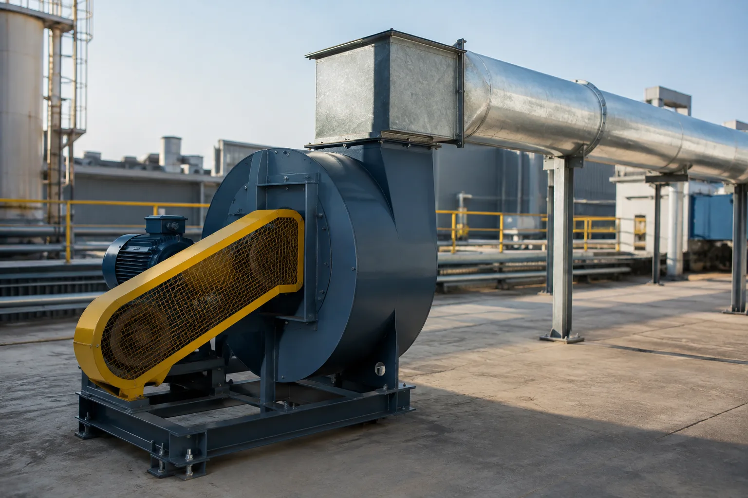
A centrifugal blower does not deliver a smooth, even airstream at its outlet. Air leaves the scroll with higher velocity on one side, and it needs a length of straight duct to even out. If an elbow, damper or transition is placed directly at the outlet, the fan cannot develop its rated performance. AMCA Publication 201, Fans and Systems, describes this loss as "system effect" and explains that it is not shown on the fan's catalogue performance curve.
In practice, this means:
- An outlet pointing directly into the duct run needs fewer bends and wastes less static pressure.
- Where an elbow cannot be avoided close to the fan, AMCA 201 guidance shows that an elbow turning in the same direction as the impeller rotation causes less loss than one turning against it.
- The wrong arrangement often forces contractors to add extra fittings, which raises the pressure the fan must overcome and can push it away from its efficient operating point.
For an industrial centrifugal blower handling dust, fumes or hot gases, a poorly matched outlet can also create dead zones where material settles in the duct, adding to maintenance work.
How to Specify the Right Arrangement: Step by Step
- Mark the fan location on your layout drawing. Note the inlet duct, the discharge duct and any wall, roof or equipment around the fan.
- Decide where the drive will sit. Consider motor access for maintenance, belt guarding and floor or platform space.
- Stand (on paper) on the drive side. All designations are read from here, not from the inlet.
- Trace the discharge duct. Is it going up through the roof, across to a stack, or down to a pit? Pick the outlet position that points most directly along this route.
- Select the rotation. With the outlet fixed, the scroll direction determines whether the fan is CW or CCW. A sketch helps avoid confusion.
- For belt drives, state the motor position. Use the W, X, Y or Z designation, or simply mark it on your sketch.
- Check the future. If the duct route may change later, ask whether the housing design allows repositioning. Some housings can be rotated and rebolted to a new position; others are fabricated for one position only.
Common Mistakes When Ordering Centrifugal Blowers
- Describing rotation from the inlet side instead of the drive side.
- Sending a photo of an existing fan without saying which side the photo was taken from.
- Placing a damper or elbow immediately at the outlet to correct a wrong arrangement.
- Specifying a replacement fan by duty only, without matching the existing arrangement, so it no longer lines up with the ductwork.
- Forgetting that a mirror-image installation (the same layout on the opposite side of a building) needs the opposite rotation.
Choosing an Industrial Centrifugal Blower Fan for Your Application
The arrangement is one part of selection. Impeller type, airflow and static-pressure requirements, air temperature and the material being handled all shape the final design. Backward-curved, forward-curved, radial and aerofoil impeller designs each suit different duties; our guide to the different types of centrifugal blowers and their uses explains where each one fits. If your blower will handle furnace exhaust, oven air or process gases, read our notes on specifying high temperature industrial fans before you finalise the arrangement, since bearing and motor positions may need to move away from the hot airstream.
For general ventilation, conveying or cooling duties, an industrial air blower built around your operating conditions will give better long-term operational performance than a standard catalogue unit forced into an awkward layout.
Working with Centrifugal Blower Manufacturers: What to Send for a Quotation

Experienced centrifugal blower manufacturers can usually confirm an arrangement quickly when the enquiry includes:
- Required air volume and static pressure at the operating point.
- Air temperature, and whether the air carries dust, moisture, fumes or corrosive gases.
- Direct drive or belt drive preference, with motor position for belt drives.
- Rotation and discharge position (for example CCW TH), or a marked sketch of the duct layout.
- Inlet and outlet connection details, and any space limits around the fan.
- Power supply details and site location.
Alfa Fans has manufactured heavy duty industrial fans in Mumbai since 1981. As a Manufacturer, Wholesaler and Exporter, our engineer-led Research and Development team designs centrifugal blowers and custom made fans to individual customer requirements, supported by accredited test facilities. We supply plants across India, including Pune, Thane, Bengaluru, Hyderabad, Chennai and Delhi NCR, and export to the UAE, Bhutan and Nepal, where we supply centrifugal blowers for industries in Nepal. Kompass featured Alfa Fans among its Top 10 Industrial Fan Manufacturers in India in 2024.
If you are unsure which arrangement your duct layout needs, send us your drawing or a simple sketch. Our engineers will confirm the rotation, centrifugal blower discharge position and drive arrangement with you before manufacture. Discuss your application requirements and request a quotation with our technical team.
Frequently asked questions
From which side is centrifugal blower rotation determined?
Rotation is determined from the drive side of the fan, which is the side with the motor or pulley. On a single-inlet blower, this is the side opposite the inlet. This follows the convention published in AMCA Standard 99-2406.
Can the discharge position of a centrifugal blower be changed after installation?
It depends on the housing design. Some housings can be unbolted and rotated to a different position, while others are fabricated for one position only. Confirm this with the manufacturer at enquiry stage if your duct route may change later.
What happens if I order the wrong rotation or discharge position?
The outlet will not line up with your ductwork, and extra elbows or transitions are usually added to correct it. These fittings close to the outlet increase system effect, so the blower delivers less air than its rated performance. In some cases the fan has to be modified or replaced.
Do I need to know the AMCA codes to order a centrifugal blower?
No. A clear sketch showing the fan location, drive side, inlet and discharge duct route is enough for our engineers to confirm the correct arrangement. The codes simply make the specification quicker and less open to misreading.
Does Alfa Fans make centrifugal blowers to custom arrangements?
Yes. Alfa Fans manufactures custom-built industrial fans and blowers to individual customer requirements, including the rotation, discharge position and drive arrangement your layout needs. Share your duty and layout details to request a quotation.